Earth-Sheltered Construction: Design Principles and Building Techniques
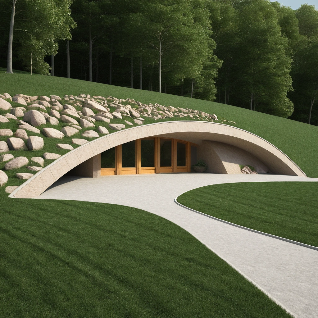
Earth-sheltered construction leverages soil’s thermal mass and insulating properties to create naturally climate-controlled living spaces with minimal energy requirements. These structures maintain comfortable temperatures year-round by coupling with earth’s stable subsurface temperatures while protecting against weather extremes. Understanding heat transfer mechanisms, soil properties, and moisture dynamics enables creation of durable, energy-efficient shelters that harmonize with natural landscapes.
Soil temperatures below frost depth remain relatively constant throughout the year, typically within 5-10°F of average annual air temperature. At 6-8 feet depth, temperature fluctuations dampen to less than 5°F annually. This thermal stability provides free cooling in summer and reduces heating requirements in winter. The phase lag between surface and subsurface temperatures means maximum cooling occurs during hottest periods and warming during coldest times.
Thermal conductivity of soil varies significantly with moisture content, density, and composition. Dry sandy soil exhibits thermal conductivity around 0.15-0.30 BTU/hr·ft·°F, while wet clay reaches 0.75-1.00 BTU/hr·ft·°F. This five-fold variation dramatically impacts heat transfer rates. Optimal soil conditions balance thermal mass benefits with insulation requirements. Dense, slightly moist earth provides ideal properties, while saturated conditions require extensive drainage and waterproofing.
Heat transfer calculations for earth-sheltered walls differ from conventional construction due to semi-infinite heat sink effects. The steady-state heat flux through earth-contact surfaces follows:
Q = k × A × (Ti – To) / x
Where Q = heat flux (BTU/hr), k = soil thermal conductivity, A = surface area, Ti = interior temperature, To = soil temperature at distance x.
Unlike above-grade construction where outdoor temperature varies dramatically, earth temperature remains stable, reducing peak heating and cooling loads by 50-80%. This load reduction enables smaller, more efficient HVAC systems or complete elimination of mechanical conditioning in moderate climates.
Structural Design for Earth Loads
Earth-sheltered structures must resist substantial lateral earth pressures and vertical loads from soil coverage. These forces exceed typical building loads by orders of magnitude, requiring robust structural systems and careful engineering. Understanding soil mechanics, load distribution, and failure modes ensures safe, durable construction.
Active earth pressure develops when walls deflect away from retained soil, mobilizing soil shear strength. For cohesionless soils, active pressure follows Rankine’s theory:
Pa = Ka × γ × H
Where Pa = active pressure, Ka = active earth pressure coefficient (typically 0.25-0.35), γ = soil unit weight (100-130 lb/ft³), H = depth below surface.
At 8 feet depth with typical soil, lateral pressure reaches: Pa = 0.33 × 120 lb/ft³ × 8 ft = 317 lb/ft²
This pressure creates substantial overturning moments requiring robust foundations and wall systems.
Reinforced concrete walls provide ideal resistance to earth pressures through monolithic construction and inherent durability. Minimum 10-inch thickness accommodates reinforcement while providing thermal mass. Reinforcement calculations follow ACI 318 requirements:
As = M / (fy × jd)
Where As = steel area, M = moment from earth pressure, fy = steel yield strength, j = internal moment arm coefficient, d = effective depth.
For typical earth-sheltered walls, #5 rebar at 12 inches on-center each way provides adequate strength. Additional reinforcement at corners and openings resists stress concentrations. Waterproofing membrane protection and proper drainage prevent corrosion ensuring long-term structural integrity.
Alternative structural systems offer different advantages:
- Insulated concrete forms (ICF) speed construction while providing integrated insulation
- Reinforced masonry with grouted cells costs less but requires careful waterproofing
- Treated wood structures work for shallow burial but have limited lifespan
- Steel culvert sections provide instant structure but limit architectural flexibility
- Shotcrete over inflatable forms enables organic shapes but requires specialized equipment
Waterproofing Systems for Below-Grade Construction
Successful earth-sheltered construction demands comprehensive waterproofing strategies addressing hydrostatic pressure, capillary action, and vapor diffusion. Unlike conventional basements where minor leakage may be tolerable, earth-sheltered living spaces require absolute water exclusion. Multi-layered approaches combining drainage, barriers, and redundancy ensure dry interiors despite continuous earth contact.
Surface water management begins with proper grading directing runoff away from structures. Minimum 5% slopes for 10 feet from walls prevent ponding. Swales and French drains intercept upslope water before reaching structures. Impermeable caps of clay or synthetic barriers above structures shed water beyond wall zones. Native plantings with deep roots stabilize soil while managing moisture through evapotranspiration.
Subsurface drainage systems relieve hydrostatic pressure before it reaches waterproofing membranes. Perimeter drains at footing level collect groundwater and direct it to daylight or sump pumps. Drain tile requires proper bedding in clean gravel with filter fabric preventing soil infiltration. Minimum 1% slope ensures positive drainage. Cleanouts every 50 feet enable maintenance access.
Waterproofing membranes provide primary moisture barriers. Sheet membranes offer consistent thickness and proven performance:
- EPDM rubber: 60-mil minimum, fully adhered or ballasted
- Modified bitumen: Multi-ply torch-applied or self-adhered
- HDPE: 60-80 mil with welded seams
- Bentonite clay: Self-healing but requires permanent hydration
Liquid-applied membranes accommodate irregular surfaces:
- Polyurethane: Seamless, flexible, 60-120 mil thickness
- Polymer-modified asphalt: Hot-applied, self-healing properties
- Crystalline concrete treatments: Penetrating, becomes integral with concrete
Protection boards shield membranes from construction damage and long-term degradation. Rigid insulation serves dual purposes of protection and thermal barrier. Drainage composites combine protection, drainage, and filtration in single products.
Passive Ventilation and Indoor Air Quality
Earth-sheltered structures require careful ventilation design to maintain healthy indoor air quality without compromising energy efficiency. Natural convection, stack effect, and wind-driven ventilation provide air exchange without mechanical systems when properly implemented. Understanding airflow physics and building pressures enables effective passive ventilation strategies.
Stack ventilation utilizes temperature-driven density differences to induce natural airflow. Warm interior air rises through high outlets while cool air enters through low inlets. The stack pressure difference follows:
ΔP = 0.0342 × h × (1/To – 1/Ti)
Where ΔP = pressure difference (inches water), h = height difference (feet), To = outdoor temperature (°R), Ti = indoor temperature (°R).
For 12-foot height with 70°F interior and 50°F exterior: ΔP = 0.0342 × 12 × (1/510 – 1/530) = 0.003 inches water
This small pressure difference requires careful inlet and outlet sizing to achieve adequate ventilation rates.
Earth tubes provide tempered ventilation air through ground coupling. Buried pipes pre-heat winter air and pre-cool summer air before entering living spaces. Optimal design parameters include:
- Pipe diameter: 8-12 inches for residential applications
- Length: 100-200 feet for maximum heat exchange
- Depth: 6-10 feet below grade for stable temperatures
- Material: Smooth-wall plastic for easy cleaning
- Slope: 1-2% toward drainage points preventing condensation accumulation
- Filters: Prevent insect and rodent entry
Cross-ventilation strategies work when earth-sheltered designs incorporate exposed walls. Opposing openings on windward and leeward sides create pressure differentials driving airflow. Window placement high on exposed walls and low on earth-sheltered sides enhances stack effect. Clerestory windows provide daylight while facilitating ventilation without compromising privacy or security.
Natural Lighting Strategies
Bringing natural light into earth-sheltered spaces challenges designers to balance daylighting with energy efficiency and structural integrity. Strategic placement of windows, skylights, and light wells illuminates interiors while maintaining earth-sheltering benefits. Understanding daylighting principles and light transmission enables bright, inviting spaces despite extensive earth coverage.
South-facing windows maximize solar gain and daylight penetration in northern hemisphere locations. Proper overhangs block summer sun while admitting winter rays. The overhang projection calculation:
P = H / F
Where P = projection, H = window height, F = factor based on latitude (typically 2.0-5.5).
Light shelves reflect daylight deep into spaces while shading near-window areas. Exterior shelves bounce light onto ceilings, providing uniform illumination. Interior shelves reduce glare while redistributing light. Optimal shelf placement at eye level divides windows into view and daylight zones.
Skylights provide overhead lighting but require careful integration with earth-covered roofs. Design considerations include:
- Structural reinforcement around openings in earth loads
- Waterproofing details preventing infiltration
- Insulated glazing minimizing heat loss
- Operable units providing ventilation
- Light wells or tubes extending through earth coverage
Tubular daylighting devices efficiently transport light through earth coverage. Rooftop collectors gather light into highly reflective tubes directing it to interior diffusers. These systems provide surprising illumination levels:
- 10-inch diameter tubes equal 300W incandescent output
- 14-inch tubes provide 500W equivalent
- 21-inch commercial units exceed 1000W
Light transmission efficiency reaches 95% through straight runs, dropping to 85% with elbows.